Parts & Tools
Camshafts
camshafts used in this project (280/272)
floor jack
jack-stands
jack-stands
cam lock timing tool
top dead center pin
fan removal tool
pliers (needle nose)
Torx 25, 30
5mm allen socket
3/8 driver short/long extension
8, 10, 13, 17mm sockets
7, 10, 24, and 32mm open end wrench
torque wrench
plenty of shop towels
Gaskets & Hardware
Real Oem
valve cover gasket #13 in above link
12 cap nuts (if needed) #8
12 cap nut washers #9
12 rubber seals #10
2 cap nuts #11
2 rubber seals #12
6 profile gaskets #14
VANOS gasket #1 Real Oem
2 crush washers (VANOS oil line) #10 Real Oem
2 crush washers (banjo bolt) #8 Real Oem
1 crush washer (chain tension bolt) #6 Real Oem
This is a good time to also do
Valve Adjustment
Spark Plug & Coil
Belts
Additional VANOS maintenance items
rebuilt VANOS with all upgraded internals
exhaust hub -cryogenically treated
cam timing tool
upgraded cam bolts
modified splined gear
sprocket
timing chain
oil pump disk
rebuilt VANOS solenoid coil pack
sealing plate repair kit
seals repair kit
rattle repair kit
rattle install tools
Getting Started
Remove air ducting, fan shrouds, fan & belly pan
jack the front of your car onto jack-stands (jack-stand DIY link)
remove the belly pan under the front of the car
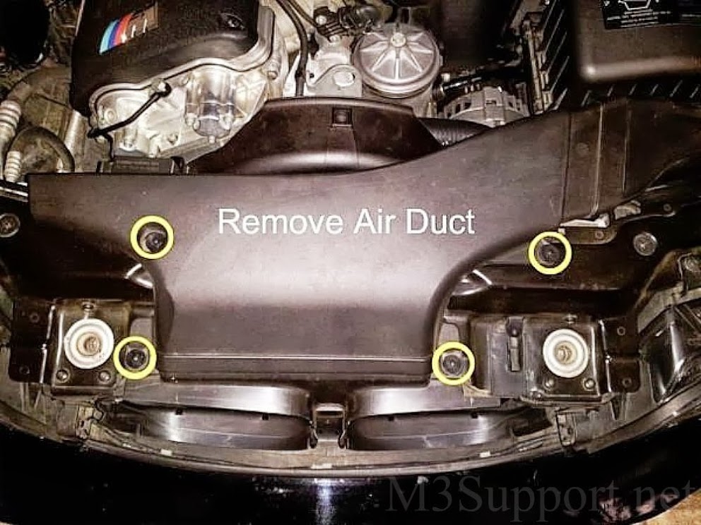
 remove kidney intake ducting starting with the corner that connects to the airbox
 using your pliers, remove the 4 clips holding down the intake ducting
pull out the top pin and remove
using your pliers, remove the 4 clips holding down the intake ducting
pull out the top pin and remove
 using our fan removal tool and 32mm wrench its time to remove the fan
place the fan removal tool onto the water pump bolts to hold it steady
use the 32mm wrench on the crank bolt and free up the fan by turning the wrench clockwise
once loose you can use the fan blades to spin the crank bolt off the thread
carefully lift the fan out from the top of the car between the block and the shroud and set it aside
using our fan removal tool and 32mm wrench its time to remove the fan
place the fan removal tool onto the water pump bolts to hold it steady
use the 32mm wrench on the crank bolt and free up the fan by turning the wrench clockwise
once loose you can use the fan blades to spin the crank bolt off the thread
carefully lift the fan out from the top of the car between the block and the shroud and set it aside


 remove rivet clip holding the two side air-guides
pull the top pin and remove
remove rivet clip holding the two side air-guides
pull the top pin and remove
 remove 3 wire clips from the top of the fan shroud. 2 on the pass. side/1 on the driver side
driver side wire clip is only removed to allow room to access the torx25
remove the 2 top torx25 bolts from the fan shroud
from under the car, remove remaining 2 torx25 bolts from the fan shroud
remove 3 wire clips from the top of the fan shroud. 2 on the pass. side/1 on the driver side
driver side wire clip is only removed to allow room to access the torx25
remove the 2 top torx25 bolts from the fan shroud
from under the car, remove remaining 2 torx25 bolts from the fan shroud


 take out the side air guide and center fan shroud
shroud should lift strait up out of the top
driver side air guide will not be removed as it has a coolant hose running through it.
take out the side air guide and center fan shroud
shroud should lift strait up out of the top
driver side air guide will not be removed as it has a coolant hose running through it.

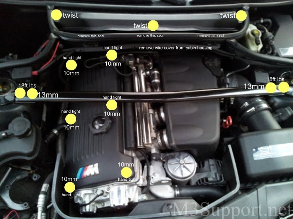
To remove the engine cover
remove strut brace
remove cabin filter
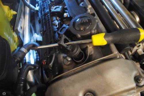
remove torx 30 bolts from inside cabin filter housing (pic below)
remove wire cover from cabin housing
remove 6 engine cover bolts
remove oil cap
remove vent hose

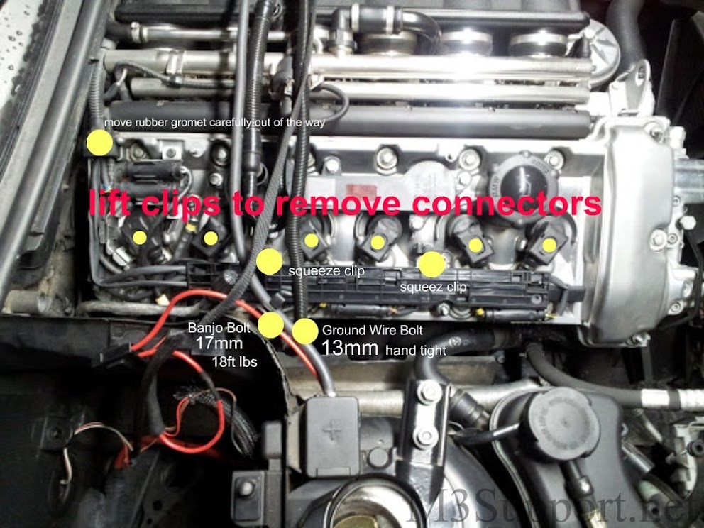
 remove banjo bolt on the side of the valve cover. (watch for the two crush washers on either side of the bolt)
remove ground wire bolt on side of valve cover
unclip the O2 sensor holder with squeeze clips
gently move rubber grommet out of the way
remove coils by disconnecting clip and pulling strait up (pic below)
remove banjo bolt on the side of the valve cover. (watch for the two crush washers on either side of the bolt)
remove ground wire bolt on side of valve cover
unclip the O2 sensor holder with squeeze clips
gently move rubber grommet out of the way
remove coils by disconnecting clip and pulling strait up (pic below)
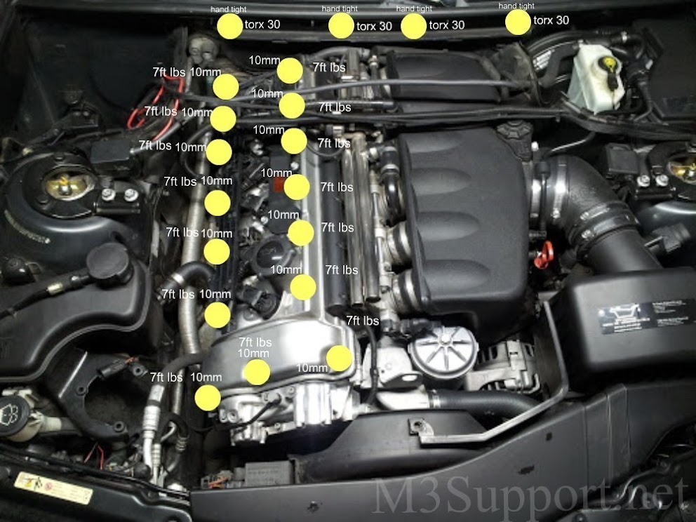
 remove 15 valve cover bolts
you can unbolt the positive battery wire if you choose to
carefully lift. (if its stuck in any way you can put your fingers in the oil fill to help pull up)
remove 15 valve cover bolts
you can unbolt the positive battery wire if you choose to
carefully lift. (if its stuck in any way you can put your fingers in the oil fill to help pull up)
 re-install the fan to manually crank the motor
crank your motor until the top dead center mark on the flywheel is in position
the first cylinder cam lobes will be facing each other when set correctly (pic below)
install the top dead center pin
re-install the fan to manually crank the motor
crank your motor until the top dead center mark on the flywheel is in position
the first cylinder cam lobes will be facing each other when set correctly (pic below)
install the top dead center pin


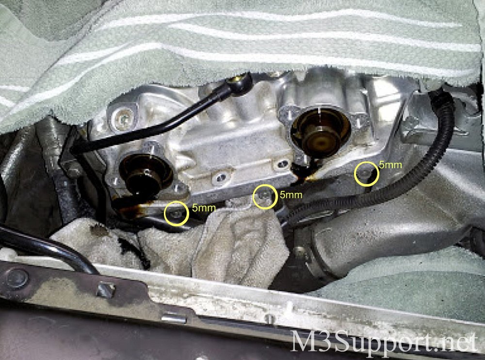
 the vanos solenoid is hiding three 5mm allen bolts which hold the vanos on. these bolts cannot be accessed until the solenoid is removed
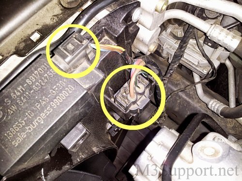
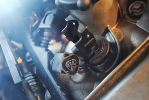
first, unclip the wire harness on the bottom left of the vanos solenoid (pic below)
make sure to cover the lower area under the solenoid, when removed a small amount of oil will drip
remove the five, 5mm bolts on top of the vanos. be careful not to let the solenoid fall when removing the final bolt
remove the two 10mm bolts on the sides of the vanos and replace them with 2 long 5mm allen bolts from the top of the vanos
only screw the long 5mm bolts in the sides partailly as they will be used to support the vanos when removing the spline shafts from the unit
remove the banjo bolt and the two, 10mm chain guard bolts located up top on the inside of the valve cover gasket
remember to keep all areas covered with towels at all times
anything dropped into the timing chain area means you will have to remove your oil pan to get it out. . not fun and very time consuming
the vanos solenoid is hiding three 5mm allen bolts which hold the vanos on. these bolts cannot be accessed until the solenoid is removed
first, unclip the wire harness on the bottom left of the vanos solenoid (pic below)
make sure to cover the lower area under the solenoid, when removed a small amount of oil will drip
remove the five, 5mm bolts on top of the vanos. be careful not to let the solenoid fall when removing the final bolt
remove the two 10mm bolts on the sides of the vanos and replace them with 2 long 5mm allen bolts from the top of the vanos
only screw the long 5mm bolts in the sides partailly as they will be used to support the vanos when removing the spline shafts from the unit
remove the banjo bolt and the two, 10mm chain guard bolts located up top on the inside of the valve cover gasket
remember to keep all areas covered with towels at all times
anything dropped into the timing chain area means you will have to remove your oil pan to get it out. . not fun and very time consuming
 here is the solenoid removed

![]() below are the Besian System sealing plate gaskets
old gaskets must be carefully scraped away without damaging the plate to install new gaskets
below are the Besian System sealing plate gaskets
old gaskets must be carefully scraped away without damaging the plate to install new gaskets


 2 long bolts are now installed in the sides to support the vanos
remove the six 5mm allen end cap bolts
pull vanos caps off or hit them lightly with a rubber mallet to remove
have shop towels ready for small amounts of oil when removing caps
with the end caps removed this will allow to push the shafts in to reach the splines when re-installing the vanos
remove the remaining three, 5mm allen bolts that were hidden behind the solenoid
2 long bolts are now installed in the sides to support the vanos
remove the six 5mm allen end cap bolts
pull vanos caps off or hit them lightly with a rubber mallet to remove
have shop towels ready for small amounts of oil when removing caps
with the end caps removed this will allow to push the shafts in to reach the splines when re-installing the vanos
remove the remaining three, 5mm allen bolts that were hidden behind the solenoid
 with all bolts removed, slide the vanos back on the long side bolts
the splined shafts are still attached to the vanos
using the 7 and 10mm open end wrenches, carefully remove each shaft from the vanos (see pic below) do NOT drop the wrench into your oil pan!
once the shafts are removed you can unscrew the side bolts and remove the vanos
with all bolts removed, slide the vanos back on the long side bolts
the splined shafts are still attached to the vanos
using the 7 and 10mm open end wrenches, carefully remove each shaft from the vanos (see pic below) do NOT drop the wrench into your oil pan!
once the shafts are removed you can unscrew the side bolts and remove the vanos


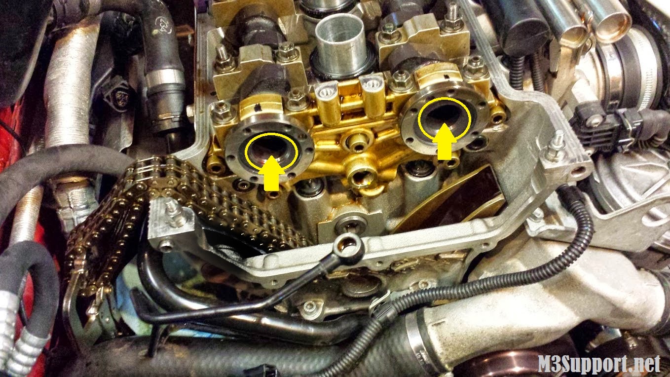
 the splined shafts can now be removed from hubs, pull them out with your hands
use the 10mm socket to remove the 6 intake/exhaust hub bolts and remove the hubs one at a time
the splined shafts can now be removed from hubs, pull them out with your hands
use the 10mm socket to remove the 6 intake/exhaust hub bolts and remove the hubs one at a time
 when removing the hubs be careful of the large washers behind them as seen in the pic below
make sure you have towels under the hubs to prevent anything from falling into the oil pan
when removing the hubs be careful of the large washers behind them as seen in the pic below
make sure you have towels under the hubs to prevent anything from falling into the oil pan
 notice the tab indents inside the hub for the large washer
 the splined shafts look the same but differ in the length of the threads on them
the exhaust spline has a longer thread shaft than the intake hub
the splined shafts look the same but differ in the length of the threads on them
the exhaust spline has a longer thread shaft than the intake hub
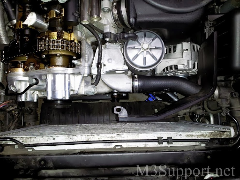
 using the 32mm socket, remove the chain tensioner to create slack in the timing chain when removing the cam sprockets
do not yet remove the sprocket
the chain tension is located to the left of the head, just below the valve cover. pictures below
using the 32mm socket, remove the chain tensioner to create slack in the timing chain when removing the cam sprockets
do not yet remove the sprocket
the chain tension is located to the left of the head, just below the valve cover. pictures below

 remove the the slide rail. pictured below

 using a sharpie marker, draw a strait line starting on the thrust bearing flange following all the way across each part up to the sprocket (the chain will lift out of your way to mark the sprocket)
this will help make re installation very simple and eliminate any confusion
using a sharpie marker, draw a strait line starting on the thrust bearing flange following all the way across each part up to the sprocket (the chain will lift out of your way to mark the sprocket)
this will help make re installation very simple and eliminate any confusion
 draw another strait line from the centering sleeve to the sprocket

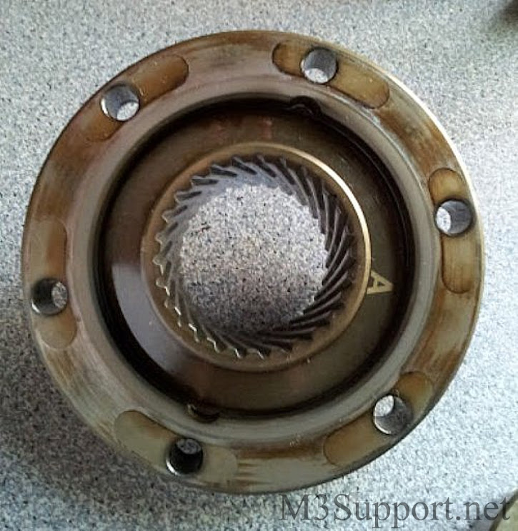
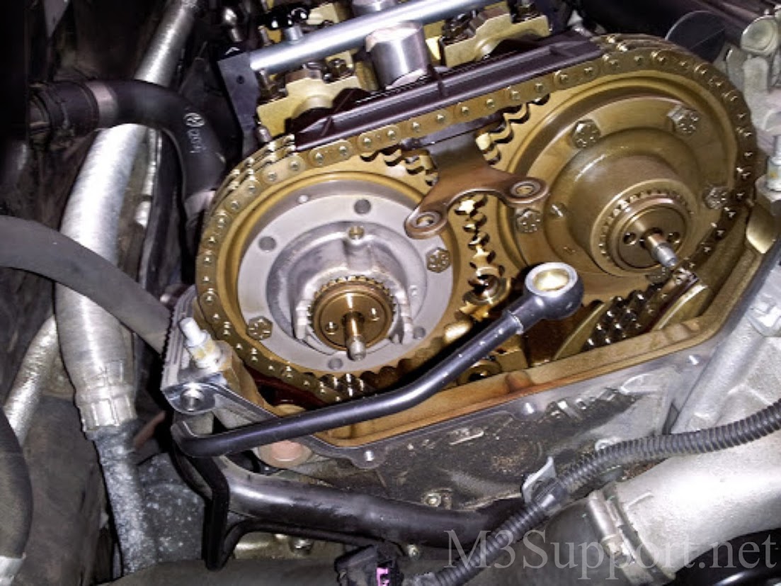
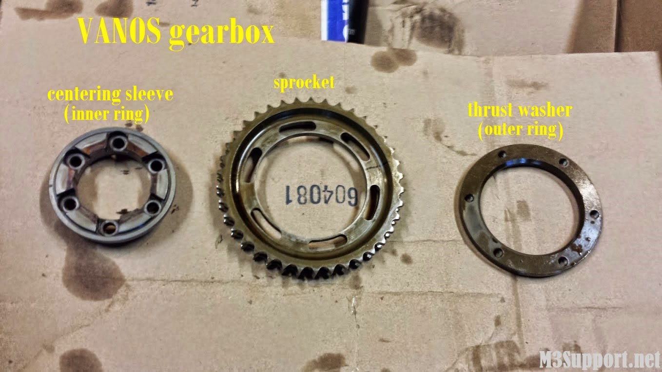 below are inlet & outlet VANOS cam gearboxes. the VANOS gearboxes which drive the camshafts, each consist of three parts as seen above, the thrust washer/outer ring, sprocket, and centering sleeve/inner ring.
 first remove the exhaust sprocket, be sure to hold the chain under tension once removed
still holding the chain under tension not allowing it to slip off of the sprocket down below, remove the intake sprocket
with the chain still under tension.. use your lock C-clamp for weight to hold the chain under constant tension and lay it to the left as pictured below
first remove the exhaust sprocket, be sure to hold the chain under tension once removed
still holding the chain under tension not allowing it to slip off of the sprocket down below, remove the intake sprocket
with the chain still under tension.. use your lock C-clamp for weight to hold the chain under constant tension and lay it to the left as pictured below
 here is a picture of the lower chain sprocket to better understand what it looks like down below
 remove the 6 center sleeve bolts then remove the centering sleeve and thrust washer on both cams
 remove the toothed sleeves from each camshaft to be re installed into the new camshafts
 toothed sleeve pictured below

 remove the bearing thrust flange pictured below
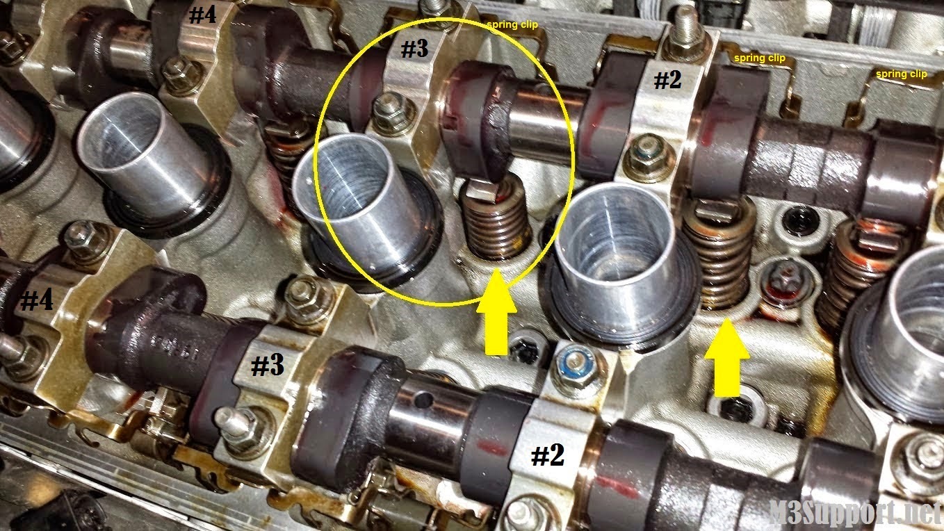
 intake cam: at top dead center notice that only cylinder #3 cam lobes are fully compressing the valve springs, take note as they will be placed in this position when re installing the new cam.
remove the spring clips located on either side of the head walls by pulling them strait up
intake cam: at top dead center notice that only cylinder #3 cam lobes are fully compressing the valve springs, take note as they will be placed in this position when re installing the new cam.
remove the spring clips located on either side of the head walls by pulling them strait up
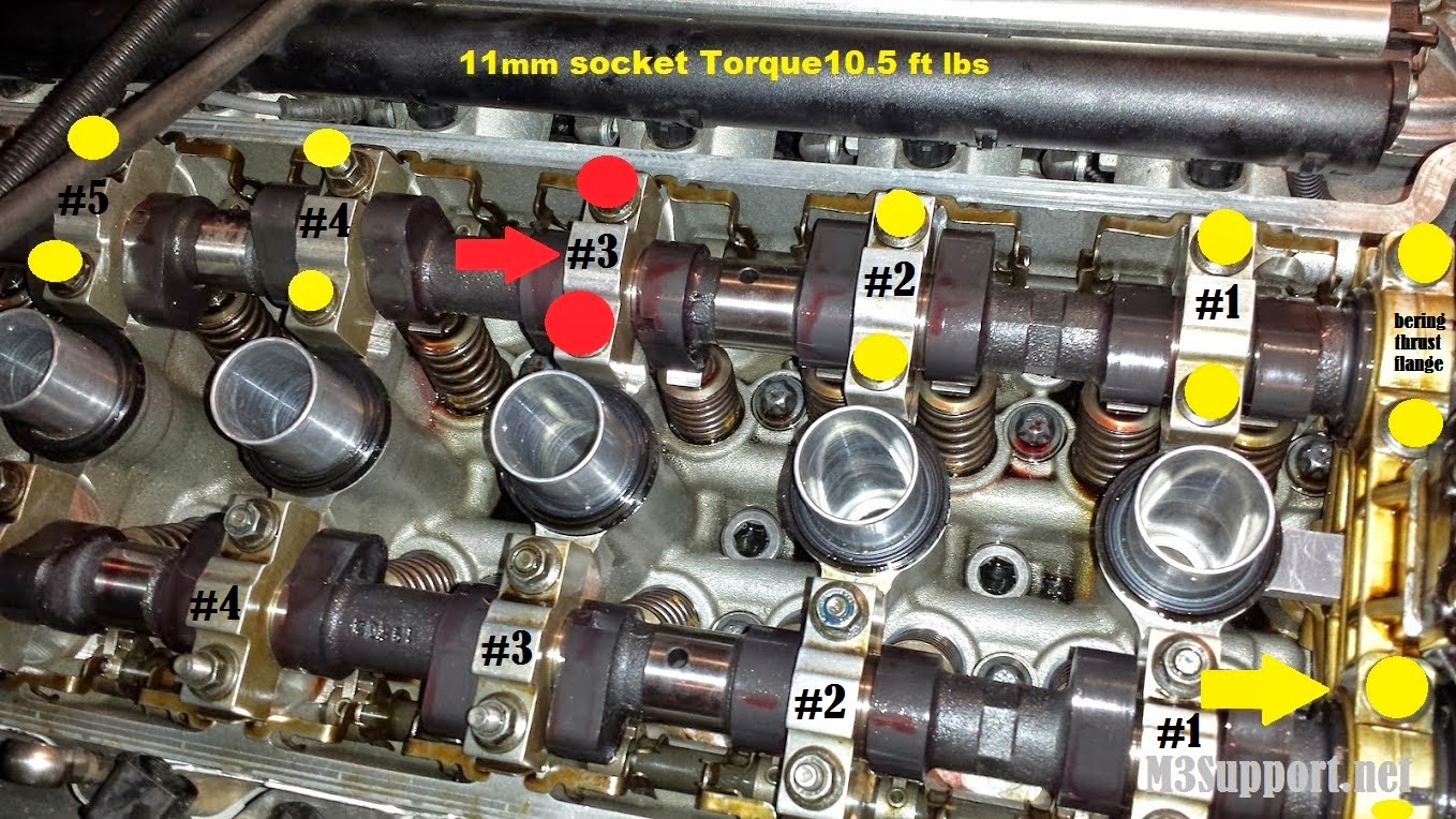
 carefully remove all 11mm bearing cap nuts, DO NOT YET LOOSEN CYLINDER #3 BOLTS-these will be removed last and be done with *extreme care
remove all bearing caps. caps are marked E2-E7 as not to be confused when re installing
have a friend you trust hold the camshaft completely still with a 24mm wrench on the camshaft. Friend: when holding the wrench be sure not to hold pressure on the cam, just keep it from turning back and forth while letting the process of decompressing take its natural course. in other words, don't lean on the wrench while holding it steady...you don't want to be responsible for putting pressure on the camshaft and snapping it because it didn't lift evenly out ;)
friend is actually holding the cam lobes still so that the lobes hold position centered on the rocker arm. the lobes will try and move slightly when the nuts are being slowly loosened
once all bearing caps and nuts are removed, remove the bearing cap nuts on cylinder #3 by making quarter turn increments on each nut starting with the nut closest to the retaining clip(longer stud), allowing the valve spring to slowly decompress as you rotate between top and bottom cap nut
remove the bearing cap, and remove the cam
carefully remove all 11mm bearing cap nuts, DO NOT YET LOOSEN CYLINDER #3 BOLTS-these will be removed last and be done with *extreme care
remove all bearing caps. caps are marked E2-E7 as not to be confused when re installing
have a friend you trust hold the camshaft completely still with a 24mm wrench on the camshaft. Friend: when holding the wrench be sure not to hold pressure on the cam, just keep it from turning back and forth while letting the process of decompressing take its natural course. in other words, don't lean on the wrench while holding it steady...you don't want to be responsible for putting pressure on the camshaft and snapping it because it didn't lift evenly out ;)
friend is actually holding the cam lobes still so that the lobes hold position centered on the rocker arm. the lobes will try and move slightly when the nuts are being slowly loosened
once all bearing caps and nuts are removed, remove the bearing cap nuts on cylinder #3 by making quarter turn increments on each nut starting with the nut closest to the retaining clip(longer stud), allowing the valve spring to slowly decompress as you rotate between top and bottom cap nut
remove the bearing cap, and remove the cam
 intake cam removed

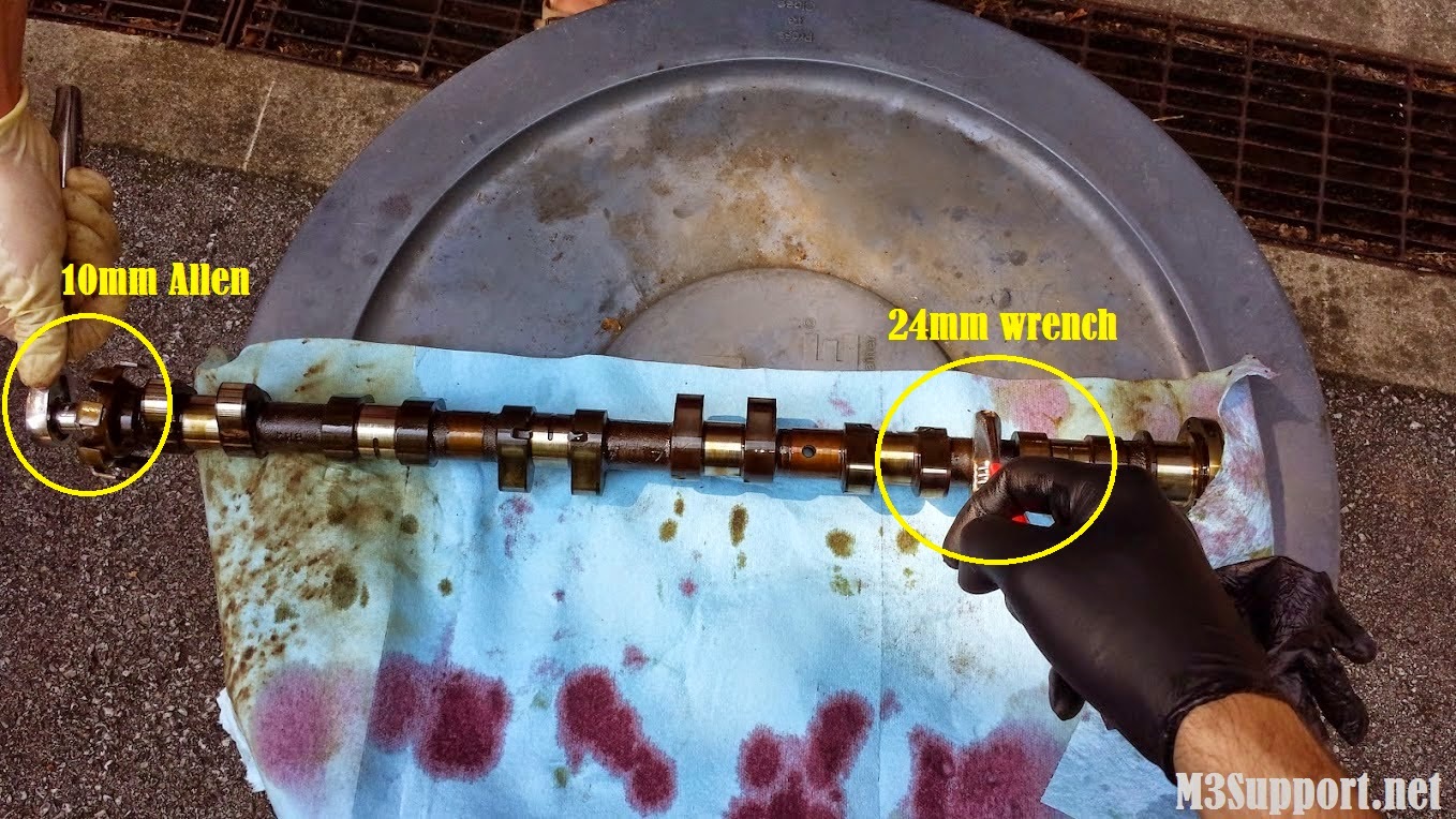
 remove the impulse sending wheel with the help of a friend
have your friend hold the cam steady using the 24mm wrench while you remove the wheel with your allen socket
install the wheel on the new camshaft
remove the impulse sending wheel with the help of a friend
have your friend hold the cam steady using the 24mm wrench while you remove the wheel with your allen socket
install the wheel on the new camshaft

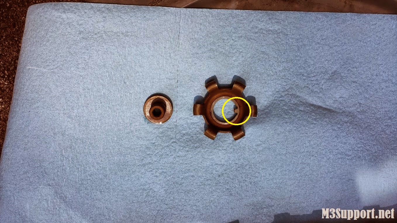
 notice the slot for the tab when installing the impulse wheel on the new cam

 install the toothed sleeve removed earlier by lining up the bolt holes
because this part was marked with a sharpie you can install it exactly as it was when removed top to bottom, although it fits correct
install the toothed sleeve removed earlier by lining up the bolt holes
because this part was marked with a sharpie you can install it exactly as it was when removed top to bottom, although it fits correct
 install the cam the same as it was removed
cylinder #3 cam lobes pointed down toward the rocker arm
with a friend holding the cam steady from turning right to left, begin to tighten the bearing cap nuts in quarter turn increments, carefully tightening until the desired 10.5ft lbs of torque. Be sure to watch that the bearing cap is evenly pulling the camshaft down toward the head. with one longer stud you might want to screw the nut down evenly before beginning the quarter turn increments
install remaining bearing caps and tighten cap nuts accordingly, do not install the thrust bearing flange as we need if off to remove and install the exhaust camshaft
follow the same instruction for the exhaust camshaft removal and install. at top dead center exhaust cylinder #2's valve springs are fully compressed with cam lobes facing down. #2 cylinder will be done last in quarter turn increments releasing the camshaft tension
install the cam the same as it was removed
cylinder #3 cam lobes pointed down toward the rocker arm
with a friend holding the cam steady from turning right to left, begin to tighten the bearing cap nuts in quarter turn increments, carefully tightening until the desired 10.5ft lbs of torque. Be sure to watch that the bearing cap is evenly pulling the camshaft down toward the head. with one longer stud you might want to screw the nut down evenly before beginning the quarter turn increments
install remaining bearing caps and tighten cap nuts accordingly, do not install the thrust bearing flange as we need if off to remove and install the exhaust camshaft
follow the same instruction for the exhaust camshaft removal and install. at top dead center exhaust cylinder #2's valve springs are fully compressed with cam lobes facing down. #2 cylinder will be done last in quarter turn increments releasing the camshaft tension
 with camshafts installed its time to re install the VANOS gearbox
on the intake side - install the thrust washer with beveled edge facing the camshaft. top should be marked with a sharpie. top and bottom are identical
install the centering sleeve and torque the bolts to 10ft lbs. part will be marked with a sharpie, again top and bottom are identical
install the sprocket and the marked line will match with the line on the centering sleeve leaving you in the same position you disassembled
on the exhaust side- install the thrust washer with beveled edge facing the camshaft
install the centering sleeve and torque the bolts to 10 ft lbs
before installing the exhaust sprocket remove your locked C-clamp from your chain and hold the chain under tension
feed your chain around the intake cam sprocket
while installing the exhaust sprocket, feed the chain around the sprocket moving both into place together
with camshafts installed its time to re install the VANOS gearbox
on the intake side - install the thrust washer with beveled edge facing the camshaft. top should be marked with a sharpie. top and bottom are identical
install the centering sleeve and torque the bolts to 10ft lbs. part will be marked with a sharpie, again top and bottom are identical
install the sprocket and the marked line will match with the line on the centering sleeve leaving you in the same position you disassembled
on the exhaust side- install the thrust washer with beveled edge facing the camshaft
install the centering sleeve and torque the bolts to 10 ft lbs
before installing the exhaust sprocket remove your locked C-clamp from your chain and hold the chain under tension
feed your chain around the intake cam sprocket
while installing the exhaust sprocket, feed the chain around the sprocket moving both into place together
 re install your chain tension bolt
install the cam lock timing tool
re install your chain tension bolt
install the cam lock timing tool

Re-installing the spline shafts
your cam timing lock pin should be installed in line with the hub you are working with before completing next steps
the first step is to install the hubs. be sure to have both washers in the back of the hubs before installing (picture below)
when bolting on the hub one at a time, install 2 bolts 180 degrees from each other and do not tighten them completely (picture below)
in the picture below you can see that the hub has a small range of clockwise/counterclockwise movement where it bolts in, allowing movement for the correct installation of the spline shafts
once you have installed two bolts, turn the hub clockwise (right) as far as it will allow
with spline in hand and hub rotated to the far right, the rule of thumb is to fit the spline shaft into the hub and rotate the hub counterclockwise until the shafts teeth slides into the hub.
the splines have a "sweet spot" on them. instead of turning the hub counterclockwise until the spline fits, rotate the spline around in your hand and keep trying to install it until it's teeth fit perfectly into the hub barley even moving the hub counterclockwise as it goes in. . that is what i call the "sweet spot".
It is important to ensure full range of motion of your splines in and out of the hubs. when done this way, you will have full range of motion eliminating any doubt moving forward that you have set your timing properly. when set properly tighten the two 10mm bolts, locking down the hub position.
when installing the shafts I prefer to set them flush with the hubs as seen in the picture below. this is how they were positioned when I disassembled in the top dead center position. more important is that the pistons are pushed completely back when the VANOS is installed, then install the end caps. upon starting the car it will put itself into full retard position, timing will be set perfectly
important: after you have re-installed your VANOS but before you install the valve cover, I strongly suggest cranking the motor by hand with the 32mm crank bolt. if you have any problems with the timing, your valves will hit and you wont be able to crank the motor by hand. this is a mandatory step to ensure not damaging your motor if something throughout this procedure was done incorrectly


Re-install the VANOS
add new VANOS gasket before bolting the unit on
support the VANOS with the 5mm long allen bolts again
line up your oil pump disc and slide the disc with VANOS into the exhaust hub tabs
connect the shafts using your 7 and 10mm open end wrenches
you can push the connecting rods toward the spline shafts where the end caps are off on the VANOS
when both spline shafts are connected you can position the VANOS in place and install the lower three, 5mm allen bolts
remove the long side bolts and install the correct 10mm side bolts
install the solenoid using the five, 5mm allen bolts, be sure to line up your sealing plate properly before bolting down
reconnect your solenoid wire clip
install the VANOS end caps by pressing them on. if you mixed them up it is okay, they are both identical (six, 5mm allen bolts)
with your VANOS now installed, crank your motor by hand to ensure your timing is correct. again, if your timing is not correct you will feel a valve hit before you complete a full rotation and stop you from cranking further. It is better to find out this way rather than crossing your fingers and turning the key later
follow picture directions above if you run into any trouble when buttoning up the rest of the motor
*when re-installing your valve cover gasket be sure to clean the surface area completely without dropping any debris into the motor. I do not use any gasket sealer and have never had an oil leak.


Disclaimer: Do this procedure at your own risk! This is offered for reference only. I disclaim all liability for direct, indirect, incidental, or consequential damages or injuries that result from the use of any of these examples, instructions, or other information.
